Universal altimeter and recovery control

The new Altimax G4

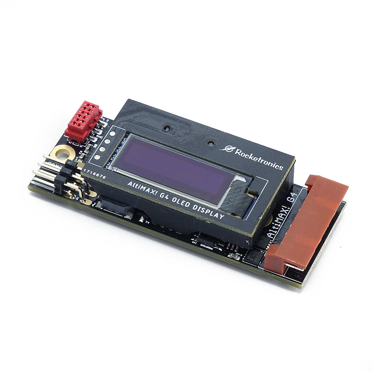
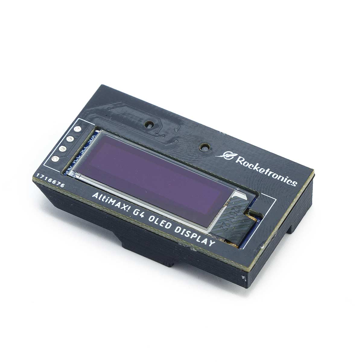
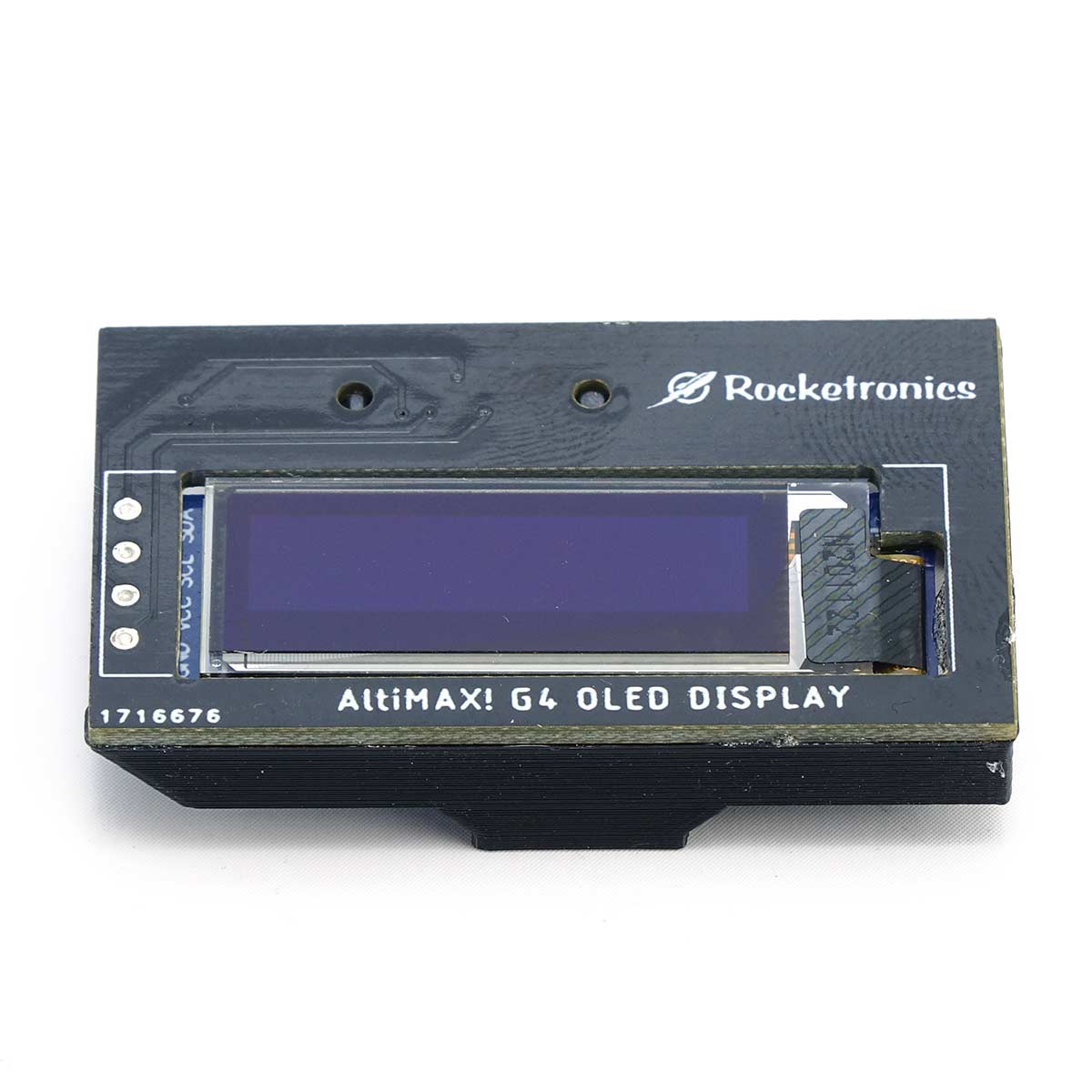
The new Altimax G4 altimeter: Suitable for the full range of model and high-power rockets. Highly integrated, it delivers a lot of function in a small space: only 68x26mm small, this altimeter offers unique functions. The 4th generation of the successful Altimax Altimeter benefits from the long experience in altimeter construction: The first Altimax Altimeter was created in 2008, and since then the technology has been regularly further developed.

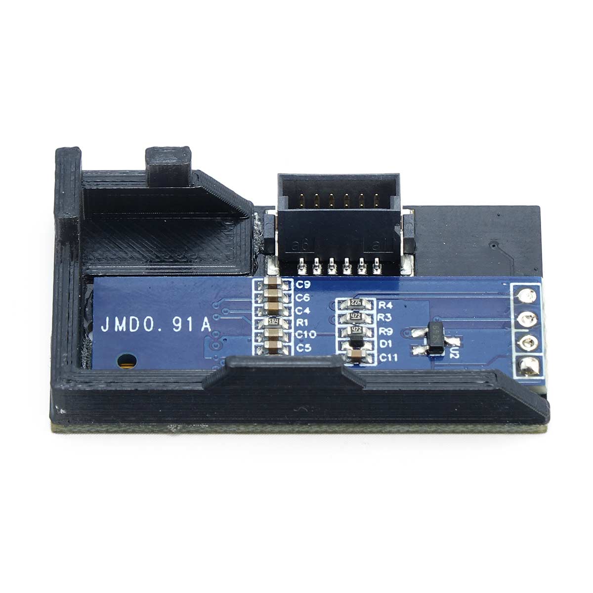
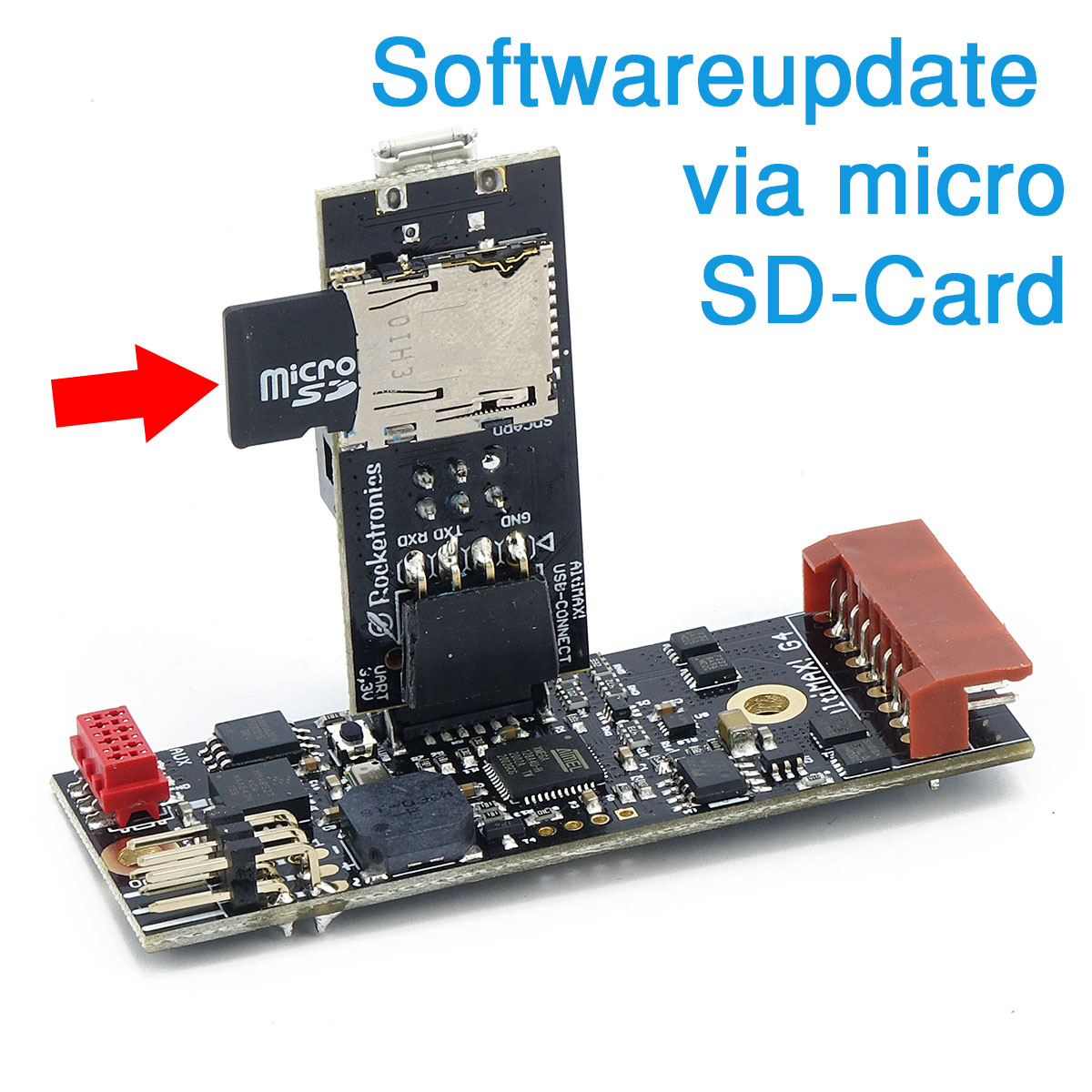
The Altimax system now consists of various altimeters with matching accessories. On this page we present the Altimax G4 with its options.

How does it work?

Basic functions

The Altimax G4 is used to record flight data and trigger functions of the rocket. For this purpose, 4 MByte of flash memory are on board to store 5 flights, while on-board voltages, air pressure and acceleration are measured and recorded. A Kalman filter generates the rate of climb from this data, allowing the exact determination of the apogee. 3 pyro and 2 servo outputs enable the execution of actions, e.g. firing of igniters (for parachute ejection) or opening of flaps. There are also 3 I/Os that can be freely assigned for control tasks. By means of an optional OLED display, LEDs and signal generator, the Altimax indicates its status. The Altimax G4 allows a wide variety of actions through its event system, multi-stage launches and multi-phase recovery, activation of transmitters, opening of flaps or ejection of cansats, every conceivable action can be implemented with the Altimax G4.

G4-Schema
akkus_450

Important for reliable function

The power supply

Power is supplied by batteries or rechargeable batteries with 7.2 – 12V. We recommend 2S LIPO batteries with 7.2V and 150-800mAh. If high current igniters are to be ignited, 3S-Lipos with 11V can also be used, then higher ignition currents are possible. The battery voltage is switched directly to the ignition outputs in case of ignition. To prevent this from causing a voltage drop and a system reset when the battery is low, the new BROWNOUTPROTECT feature has been introduced: It monitors the battery voltage and regulates the ignition current so that the voltage does not drop below about 6V, thus ensuring safe ignition and preventing a system reset. Internally the Altimax runs with regulated 3.3V, the servos are supplied with 5V from a voltage regulator.

Control outputs

Ignition and servo outputs

The Altimax has a number of outputs with which control tasks can be performed:

  • 3 pyro outputs with a continuous switching power of up to 15A, 40A peak
  • 2 servo outputs with 5V max. 1A for RC servos with JR connector
  • 3 digital on/off outputs with 3,3V level and max. 20mA output current.

This can be used to fire igniters of all kinds, open flaps via servos or release parachutes (e.g. via a servo release).
The I/O can be used for various control purposes, e.g. switch on an external signal generator after landing, activate a transmitter for tracking or be used as input for event control.

NEW: The pyro outputs are thoroughly checked for function by FETCHECK at startup, this ensures that the transistors are intact.

Each output is assigned an action, each input an event that is triggered when the level at the input changes.

zuender
sensors

Eyes and ears of the altimeter

The sensors

There are 2 sensors on board, an air pressure sensor and an acceleration sensor. The air pressure sensor measures the air pressure with high accuracy, the software calculates the flight altitude from this. The resolution is approx. 15 cm. The acceleration sensor has a measuring range of +- 120G and can thus also measure very strong accelerations. The digital measurement data is filtered by a Kalman filter, this filter provides the vertical velocity, together with altitude and acceleration this flows into the sequence control. The software then decides on the basis of the data in which position the rocket is and reacts accordingly.

Universally usable

The Altimax event system

The Altimax G4 has an event system unique to altimeters. It allows the linking of input signals, events and timers with actions and thus allows a very flexible response to attitude changes and times. Events are generated by level changes at the 3 digital inputs, by reaching certain flight positions (e.g. reaching the peak), or by the expiration of one of the three timers. Internally, a series of events is generated by the flight attitude evaluation. The linkage is done via the PC software or the LCD terminal. There you can link every event with every possible action via a matrix in the settings! So there are more than 11000 combinations available, which are nevertheless very easy to set.

set1en

Analysis and flight data

Possible events

Events are triggered based on the analysis of the flight data. The following events are possible:


  • Start (acceleration) – detected by acceleration
  • Start (pressure) – detected by pressure change
  • Combustion closure – when the thrust of the engine ends
  • Machdelay – When the Machdelay timer has expired
  • Altitude ascent – Altitude exceeded during rocket ascent
  • Timer 1 End – Sequence of an adjustable timer
  • Timer 2 End
  • Timer 3 End
  • Apogee acceleration – Apogee point calculated by acceleration
  • Apogee pressure – Apogee point calculated by pressure change
  • Height descent – Altitude undershot after reaching the apogee point
  • AUX1 level change – When the level of input AUX1 changes
  • AUX2 level change – Dito for AUX2
  • AUX3 level change – only if the AUXn is also set as input!
  • Landing

Analysis and flight data

Possible actions

The following actions can be linked to an event:

  • Timer 1 Start – Starts timer 1
  • Timer 2 Start – Starts timer 2
  • Timer 3 Start – Starts timer 3
  • PYRO 1 – Activates output Pyro 1
  • PYRO 2 – Activates output Pyro 2
  • PYRO 3 – Activates output Pyro 3
  • SERVO 1 – Activates output servo 1
  • SERVO 2 – Activates output servo 2
  • AUX1 – Activates digital output AUX1 (if this is set as output!)
  • AUX2 – Activates digital output AUX2 (if this is set as output!)
  • AUX3 – Activates digital output AUX3 (if this is set as output!)

Successful operations at the Cansat competition

cansat

Thousands of rocket launches have been successfully performed with the Altimax Altimeters. Large as well as small projects flew with the Altimax, worldwide from Australia to USA they are in use, from black powder to hybrid engines everything was there. Among other things, it ensures accurate launching of the Cansats and safe two-phase recovery at the German Cansat Competition. In the joint projects of the AG Model Rockets, Altimax Altimeters ensured safe recovery of the Proton and the Saturn V. The Altimax is also used in research and teaching, and many universities in Europe use it in rocket projects. Last but not least, it has been used by the developer in all rockets since the beginning, all Level 1 – Level 3 rockets flew successfully with it.

Comparison of the currently offered altimeters

  AltiMAX G4 Altimax Simply 2018
Dimensions 68×26 mm 35×21 mm
Weight 13 g 4,6 g
Input voltage: 7,2 – 12 V 3,3-12 V
Power consumption* (without servos and terminal) Ca. 23 mA ca. 5 mA
Pressure range 10 – 1200 hpa 0 – 1200 hpa
Height range -170 – 31000 m   ü.N.N -170 – 31000 m   ü.N.N
Memory 4 Mbyte
Number of ignition channels 3 2
Number of servo channels 2
Number of additional I/Os 3  
Ignition duration 3 Sec 1 Sec
Ignition voltage =Battery voltage =Battery voltage
Max. Ignition current 15A  9A
Accelerometer Yes +-120G Nein
Servo supply 5V, max 1 A
     
Resolution height ca. +- 0,15 m ca. +- 0,15 m (1m Ausgabe)
Resolution acceleration +- 0,04G
Sampling rate pressure 204.800 sps 204.800 sps
Sampling rate acceleration 200 sps
Storage rate** 200 sps / 40 sps
Storage duration approx. 5 Flights a 10 min.


.

Accessories for the Altimax G4

For setting and evaluation

Free PC software

A free software for Windows is offered. With it, the settings of the Altimax can be changed and tests can be performed. The event system is very easy to edit here, you just click together the connection from event to action.

Tests of the outputs and setting of the servo positions can be reached by mouse click. In addition the software of the data evaluation serves, the flight data can be read out over the USB connector and then be represented graphically. Events and actions are also displayed. Export functions allow the export as image or Excel table. The data can also be saved and reopened later.

The software is free of charge and available in english and german language.

Direct display of the status

OLED-Display

An optionally available OLED display can be plugged directly onto the connector port. It displays status data such as battery voltage, igniter status and last altitude reached. It can remain plugged in and then displays the altitude reached after a landing.

Connection to PC, SD card and LCD terminal

USB Connector

USB: The G4 Connector is plugged onto the multi-pin connector, you cannot plug it in the wrong way around. The connector allows connection to a PC (WindowsXP-10) via USB to read out flight data and make settings / tests.
LCD terminal: There is also a 6-pin header on the connector to accept the plug of the LCD terminal. One pin is intentionally missing there as reverse polarity protection.
MICROSD CARD: A socket for a micro SD card is located on the back. Insert a micro SD card with a software update for the Altimax G4 here to update the software when the altimeter starts. The process takes only 5 seconds, all settings are preserved

Change settings without PC

LCD-Terminal

The LCD terminal is connected via the USB connector. To do this, the terminal’s pin plug is inserted into the socket on the connector and then the connector is plugged into the Altimax G4. The terminal is only recognized when rebooting, so the Altimax must be switched on after plugging it in!

Safe switching on via magnet

Magswitch

Very small magnetic switch for activating electronic assemblies such as altimeters, data loggers, etc. The switch is activated by holding a magnet for 1 second. Only when a magnetic field is applied again for 2 seconds without interruption, it is switched off. A bright red LED indicates the switching on.

So can be activated through the model housing, without flaps, switches or holes. Just hold the magnet on it and off you go!