
Connecting & Commissioning JMC Motors
JMC motors with integrated driver are quickly wired: they only need a supply voltage and a control signal. This page summarises the most important points on power supply, wiring and first commissioning.
1. Supply Voltage & Power Supply
Each motor has a nominal voltage (24 / 36 / 48 / 72 V depending on frame size). Use a power supply that delivers this voltage. For milling machines, the power supply should be able to provide briefly about 2/3 of the combined current of all motors; since the axes never all run at full load simultaneously, this works out very well.
Charge Capacitor Against Voltage Spikes
Decelerating servo motors feed energy back, which can briefly raise the supply voltage. A DIN-rail charge capacitor module buffers these spikes and protects the power supply and motor electronics. We offer three types: 4700 µF / 63 V, 9400 µF / 63 V and 9400 µF / 80 V. For power supplies with higher continuous current, a 9400 µF module is recommended; make sure the voltage rating (63 V or 80 V) is above your supply voltage. All models can be found under charge capacitors in the shop.
2. Control Signal: Step/Dir or Pulse
The motors are controlled via step/dir signals from your CNC controller – compatible for example with Estlcam terminal adapters, Eding CNC, CSMIO and many other controllers. The signal inputs for DIR, PUL and ENA are built with optocouplers and accept a signal voltage of 3.3 V to 24 V. At signal voltages above 5 V, a suitable series resistor must be connected in series to limit the input current of the optocoupler. For clean, fast signal transmission to several motors, we offer matching RJ45 adapter sets that considerably simplify the wiring.
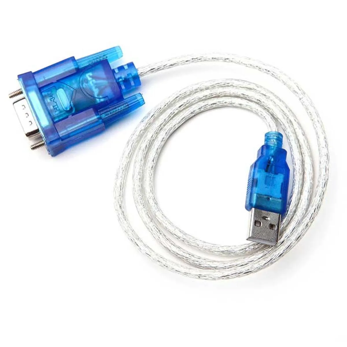
3. Parameterisation via RS232 (optional)
Many JMC motors can be fine-tuned via an RS232 interface (e.g. current, microstep resolution, control behaviour). For this you need a USB-RS232 converter and the matching RS232 cable. As delivered, the motors are already sensibly preconfigured and usually run without further adjustment.
4. First Commissioning – Checklist
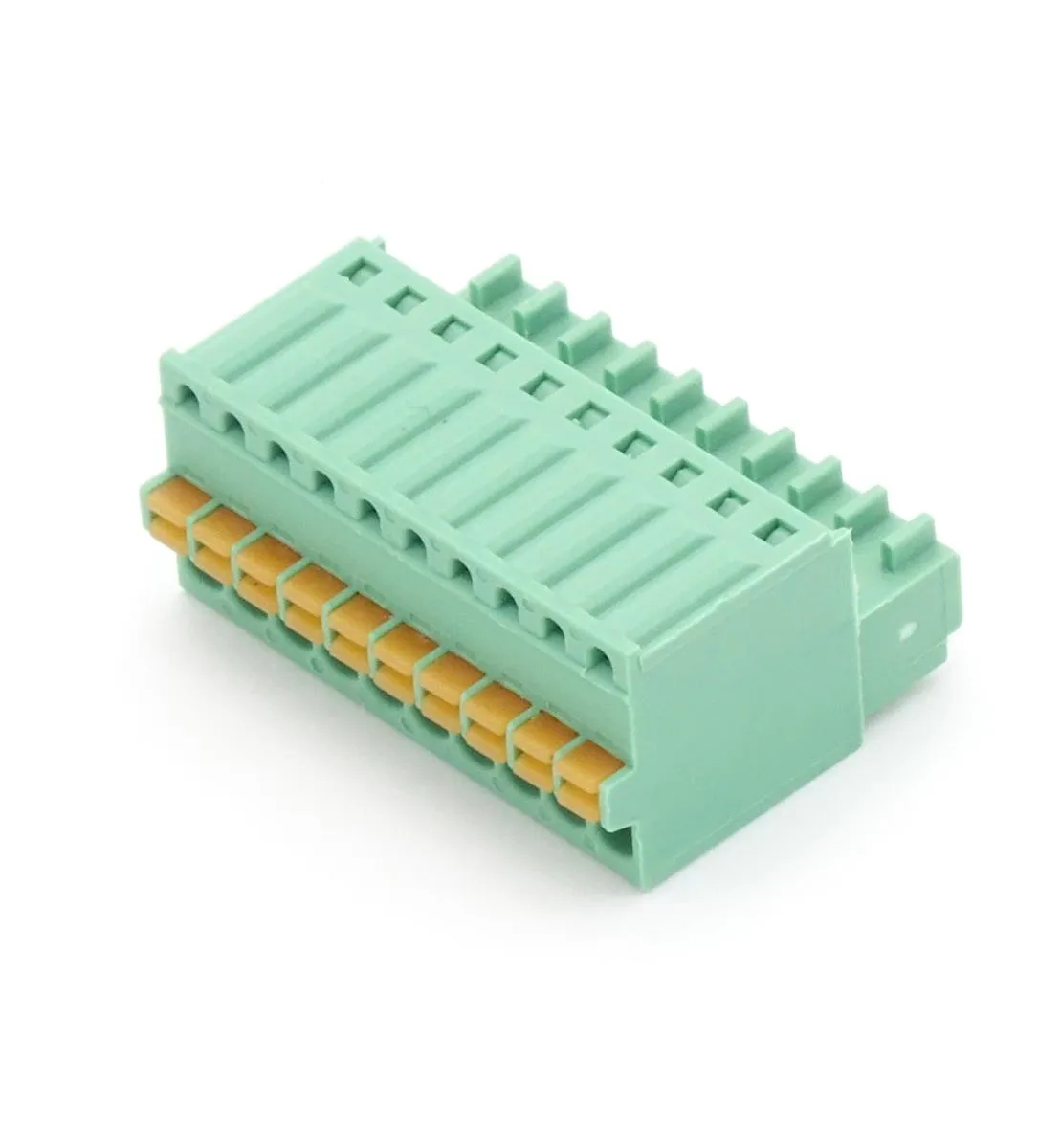
Proceed in a structured way for the first commissioning: check supply voltage and polarity, wire the step/dir signal correctly, first test the motor without load and at low speed, check direction of rotation and homing, then gradually increase acceleration and speed. Make sure the connectors are firmly seated – the matching PCB connectors in various pin counts can be found in the accessories.
⚠ Safety notes for commissioning
During first commissioning, incorrect settings can cause unexpected and forceful movements. Therefore note:
- First tests without load and at reduced speed. If possible, disconnect the motor from the mechanics or operate with a large safety distance until direction of rotation and behaviour are confirmed.
- Increase acceleration and maximum speed gradually. Values that are too high can lead to step losses, jerky movements or a “runaway” drive that moves the axis uncontrollably.
- Set up and test limit and reference switches before the first move. They are the last safeguard against overrunning the travel limits and against collisions.
- Keep the emergency stop within reach. Make sure the system can be de-energised immediately at any time, and never reach into the travel range while the motors are active.
- Wrong direction of rotation or swapped axes can cause movements in the wrong direction – check each axis individually.
- Electrical safety: only change the wiring when de-energised. Charged capacitors can still carry voltage after switch-off.
The Most Important Connection Signals in Detail
Regardless of frame size, all JMC motors work with the same set of control signals. The pulse signal (PUL/Step) sets the steps or the target position, the direction signal (DIR) determines the direction of rotation. The enable signal (ENA) switches the motor inactive: if an active ENA signal is present, the power stage is switched off and the shaft can rotate freely. If the signal is absent, the motor is activated and holds its position. This logic can be inverted via the parameters if needed. The alarm output (ALM) is designed as an open-collector output and becomes active as soon as a fault condition occurs – for example on blockage, overcurrent, over-temperature or excessive position deviation. This allows the controller to detect the fault and stop the machine in a controlled manner.
Reverse-Polarity Protection on iHSSC Models
The closed-loop models with the type designation iHSSC have additional reverse-polarity protection on the supply voltage. If the power supply is accidentally connected with reversed polarity, this circuit protects the electronics from damage – a practical safety plus, especially during initial commissioning and in service cases.
Matching Accessories for Commissioning
Power supplies, capacitors, adapters, connectors and cables – all from stock.